

- U-I-R-Messtechnik
- Signalgeneratoren
- Frequenzmesser
- Oszilloskope
- Analyzer & Wobbler
- Leistungsmesstechnik
- R-L-C-Messtechnik
- Prüftechnik, Spezialmesstechnik
- Energieversorgung
- Funktechnik
- Radar & GHz
- NF & HiFi
- Licht & Optik
- Steuer- & Regelungstechnik
- Telefonie & Kommunikation
- Mechanik
- Avionik
- Sammeln & Seltenes
- Bauelemente
- ...
- Röhrenliste
- Manuals & Schaltpläne
- sonstiges...
Informationen

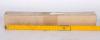
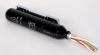
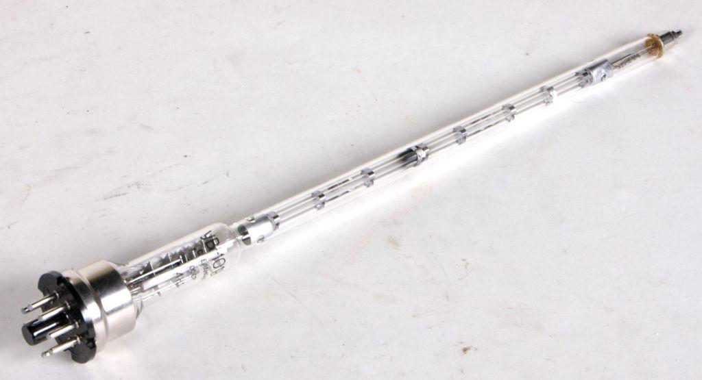
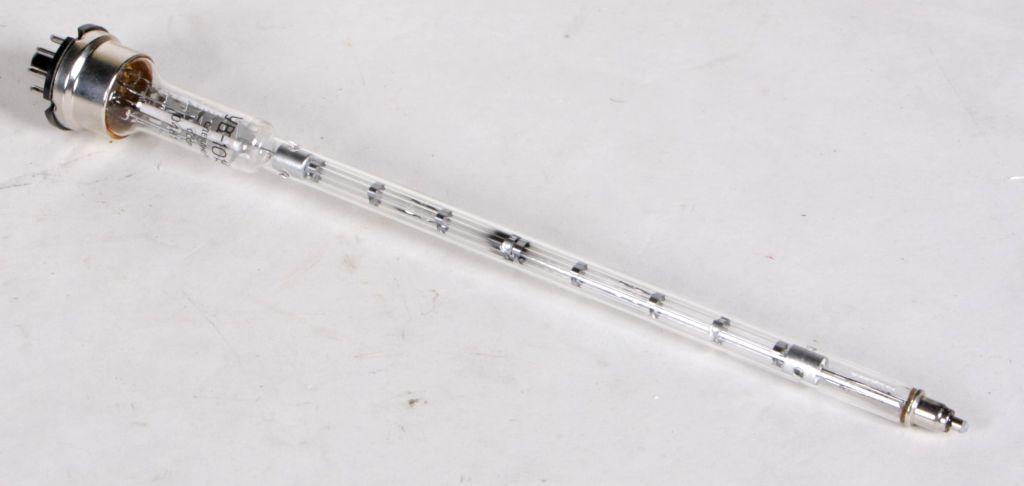
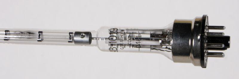
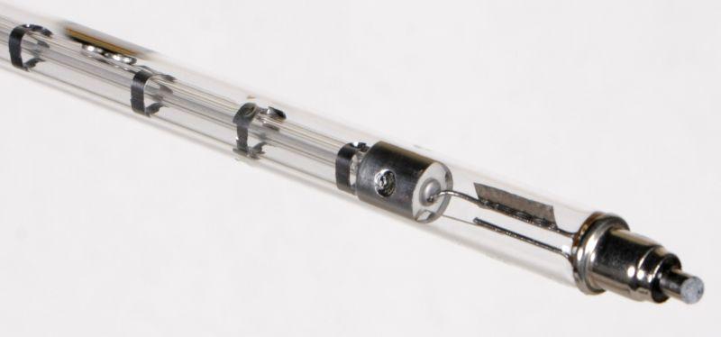
Wanderfeldröhre UV-1019
Art.Nr.: roe-wan-0005b


Hochfrequenz- Leistungsverstärker UV-1019, russische Bezeichnung УВ-1019.
Technical datas below.
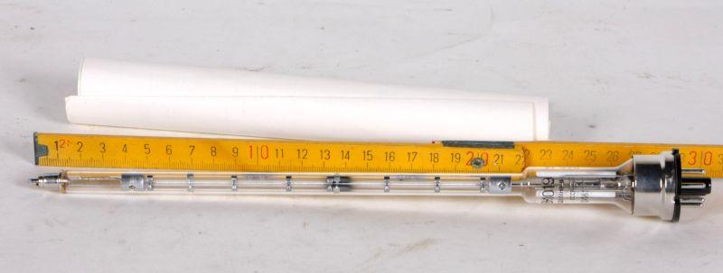
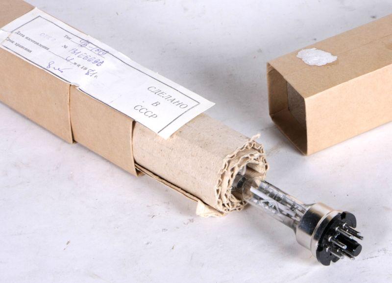
Wanderfeldröhre UV-1019, УВ-1019
* Hochfrequenz- Leistungsverstärker* original verpackt, NOS, Baujahr 1975/87
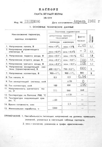
Technische Daten Wanderfeldröhre UV-1019, :
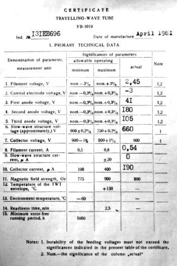
TRAVELLING-WAVE TUBE UV-1019
PRINCIPAL TECHNICAL DATA
| Denomination of parameter, measurement unit | Significances of parameters | ||
| allowable operating | actual | ||
| minimal | maximum | ||
| 1. Filament voltage, V | nom-3% | nom+3% | |
| 2. Control electrode voltage, V | nom-0.3% | nom+0.3% | |
| 3. First anode voltage, V | nom-0.3% | nom+0.3% | |
| 4. Second anode voltage, V | nom-0.3% | nom+0.3% | |
| 5. Third anode voltage, V | nom-0.3% | nom+0.3% | |
| 6. Slow-wave structure voltage, approximately, V | 600-0.2% | 750+0.2% | |
| 7. Collector voltage, V | 900-1% | 900+1% | 900 |
| 8. Filament current, A | 0.5 | 0.8 | |
| 9. Slow-wave structure current, µA | – | ±20 | |
| 10. Collector current, µA | 100 | 400 | |
| 11. Operating wavelength range, cm | 3 - 3.55 | – | 3 - 3.55 |
| 12. Noise factor, unit | – | 10 | |
| 13. Power gain, dB | 17 | – | |
| 14. Magnetic field strength, Oe | 775 | 900 | 800 |
| 15. Total starting time, min | – | 2.5 | – |
| 16. Minimum operating time, h | 2500 | – | – |
| 17. Temperature at the TWT's envelope, °C | – | +130 | – |
| 18. Ambient temperature, °C | -60 | – | |
Notes:
- Instability of the feeding voltage must not exceed the significances indicated in the present table.
- Non-nominal significance of a parameter indicated in the column "Significances of parameters actual".
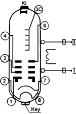
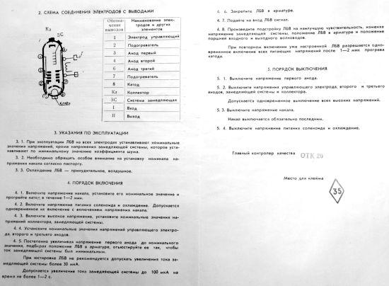
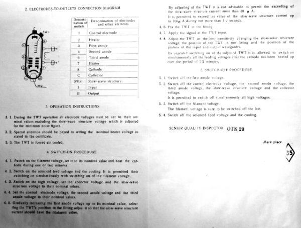
ELECTRODES-TO-LEADS CONNECTION DIAGRAM
 |
Designation of leads | Denomination of electrodes and other elements of diagram |
| 1 | Control electrode | |
| 2 | Heater | |
| 3 | First anode | |
| 4 | Second anode | |
| 6 | Third anode | |
| 7 | Heater | |
| 8 | Cathode | |
| Kl | Collector | |
| 3C | Slow-wave structure | |
| I | Input | |
| II | Output |
OPERATION INSTRUCTIONS
During the TWT operation all electrode
voltage must be set to the nominal values excluding the slow-wave
structure voltage which is adjusted by the minimum value of the noise
factor.
The nominal electrical regime is chosen by the producer for a given
specimen of the TWT in the following limits:
| filament voltage from | 2.3 to 3 V; |
| control electrode voltage from | -10 to 0 V; |
| first anode voltage from | 20 to 80 V; |
| second anode voltage from | 100 to 300 V; |
| third anode voltage from | 100 to 350 V; |
| slow-wave structure voltage from | 600 to 750 V; |
| collector voltage of | 900 V |
| magnetic field strength of | 800 Oe. |
All voltages are given concerning the cathode.
Special attention should be paid to setting the nominal filament
voltage as stated in the certificate.
The TWT is forced air cooling.
SWITCH ON PROCEDURE
Switch on the filament voltage, set its nominal value and
heat the cathode during 1 - 2 min.
Switch on the solenoid feed voltage and the cooling.
It is permitted their switching on simultaneously with the switching on
of the filament voltage.
Switch on the high voltage, set the collector voltage and the slow-wave
structure voltage to their nominal values.
Set the control electrode voltage, the second anode voltage and the
third anode voltage to their nominal values.
Gradually increasing the first anode voltage to the nominal value,
selecting the TWT's position in the solenoid, adjust it so that the
slow-wave structure current should have the minimum value.
When adjusting the TWT it is not advisable to permit the exceeding of
the slow-wave structure current more than 30 µA.
It is permitted to exceed the slow-wave structure current up to 100
µA during not more than 1 - 2 s.
Fix the TWT in the solenoid.
Apply the signal at the TWT input.
Adjust the TWT at the best sensitivity by changing the slow-wave
structure voltage the TWT's position in the solenoid and the position
of the pistons of the input and output waveguides.
By repeated switching on of the adjusted TWT it is allowed to switch on
simultaneously all feeding voltages after the cathode has been heated
during 1 - 2 min.
SWITCH OFF PROCEDURE
Switch off the first anode voltage.
Switch off the control electrode voltage, the second anode voltage, the
third anode voltage, the slow-wave structure voltage and the collector
voltage.
It is permitted to switch off simultaneously all high voltages.
Switch off the filament voltage.
The filament voltage is sure to be switched off the last.
Switch off the solenoid feed voltage and the cooling.
Wanderfeldröhre UW-1019, УВ-1019:
Datenblätter russische Wanderfeldröhre UW-1019, УВ-1019:
Allgemeines zur Wanderfeldröhre:
Die Wanderfeldröhre gehört zu den Laufzeitröhren.
Eine Laufzeitröhre ist eine Elektronenröhren zur Erzeugung oder -Verstärkung von Mikrowellen. Laufzeitröhren finden also ihre Anwendung in der Hochfrequenztechnik.
Bei den Laufzeitröhren sind die Entladungssyteme so konstruiert, daß Laufzeiteffekte das Funktionieren der Röhre bewirken.
Zunächst wird eine homogene Elektronenströmung konstanter Geschwindigkeit erzeugt, deren Elektronen dann einem steuernden elektrischen HF-Feld ausgesetzt werden, in dem sie je nach Startphase beschleunigt oder verzögert werden.
Bei den Langzeitröhren unterscheidet man zwischen Triftröhren und Lauffeldröhren.
In der Praxis verwendete Laufzeitröhren sind Zweikammer- und Mehrkammerklystrons, Wanderfeldröhren, Rückwärtswellenröhren und Magnetrons sowie gewisse Hybridformen wie Wanderfeldklystrons.
Die Wanderfeldröhre dient der Verstärkung elektrischer Signale. Der Elektronenstrahl wird durch ein nicht mitgezeichnetes homogenes axiales Magnetfeld, herrührend von einem auf möglichst gewicht- und raumsparende Weise gestalteten Elektro- oder Permanentmagneten, oder auch von einem periodischen Permanentfeld, fokussiert und zum Elektronenauffänger geführt. Die zu verstärkende HF-Leistung wird katodenseitig auf die Wendelleitung gekoppelt, wohingegen die verstärkte HF-Leistung kollektorseitig ausgekoppelt wird.
Wanderfeldröhren werden wegen ihrer guten Linearität (Breitbandeigenschaften) und Rauscharmut und wegen des großen Leistungsspielraumes mannigfaltig eingesetzt, z.B. in Bodenstationen für Satellitenfunk mit Dauerstrichleistungen im kW-Bereich, als Satellitenröhren (bis herab zu 20 W interessant; 650g Masse) und für Richtfunktechnik (2700 Kanäle bei 6 ... 7 GHz) sowie für die Radar-Impulstechnik mit Impulsleistungen bis zu mehreren MW. Die Wanderfeldröhre ist ein weit verbreitetes Bauteil in der Radartechnik.
Der Frequenzbereich der Verstärkung ist kleiner als 0,05 dB x MHz hoch -1 im ganzen Bereich, bei optimaler Frequenz sogar noch eine Zehnerpotenz geringer.
Die Zuverlässigkeit der Wanderfeldröhren ist groß, die Lebensdauer dieser Laufzeitröhren liegt bei Größenordnungen von 20 000 Stunden.