

- U-I-R-Messtechnik
- Signalgeneratoren
- Frequenzmesser
- Oszilloskope
- Analyzer & Wobbler
- Leistungsmesstechnik
- R-L-C-Messtechnik
- Prüftechnik, Spezialmesstechnik
- Energieversorgung
- Funktechnik
- Radar & GHz
- NF & HiFi
- Licht & Optik
- Steuer- & Regelungstechnik
- Telefonie & Kommunikation
- Mechanik
- Avionik
- Sammeln & Seltenes
- Bauelemente
- ...
- Röhrenliste
- Manuals & Schaltpläne
- sonstiges...
Informationen

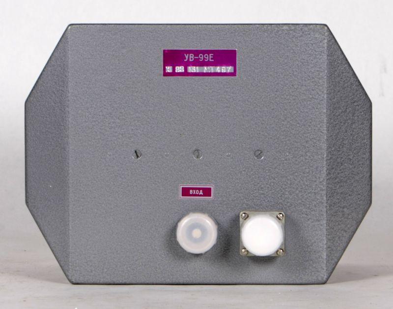
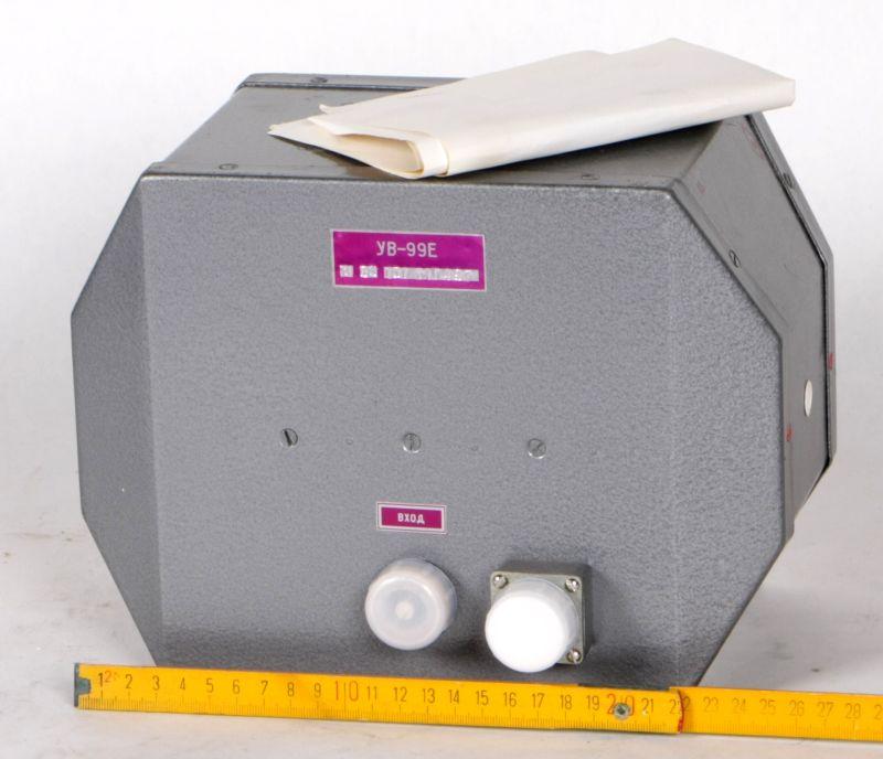
Wanderfeldröhre UV-99E
Art.Nr.: roe-wan-0028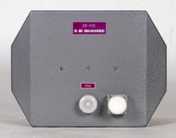


* Hochfrequenz- Leistungsverstärker
* Technical datas below.
Wanderfeldröhre UV-99E, УВ-99Е
Technische Daten Wanderfeldröhre UV-99E, УВ-99Е:
TRAVELING - WAVE TUBE UV-99 E
PRINCIPAL TECHNICAL DATA
| Denomination of parameter, measurement unit | Significances of parameters | ||
| allowable operating | actual | ||
| minimal | maximum | ||
| 1. Divider voltage,V | nom-1% | nom+1% | |
| 2. Filament current, A | nom-1% | nom+1% | |
| 3. Slow-wave structure current, µA | – | 75 | |
| 4. Collector current, µA | – | 200 | |
| 5. Operating wavelength range, cm | 12.9-14.05 | – | 12.9-14.05 |
| 6. Noise factor, unit | – | 3.5 | |
| 7. Power gain, dB | 20 | 30 | |
| 8. Total starting time, min | – | 2 | |
| 9. Minimum operating time, h | 1000 | – | |
| 10. Ambient temperature, °C | -50 | +80 | |
Notes:
- Instability of the power supplies of the filament and the divider must not exceed ±1%.
- Nom-nominal significance of a parameter indicated in the column "Significances of parameters actual".
- The filament voltage covers 1.7-2.3V.
- The nominal value of the divider voltage covers 390-410 V, the filament current covers 0.2-0.26 A.
- The stabilization according to the filament voltage is allowed in the filament power supply (instability of the filament voltage is not worse than that indicated for the filament current).
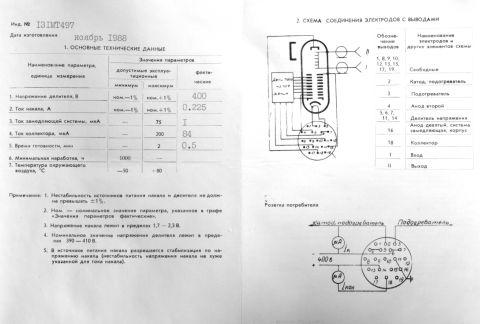
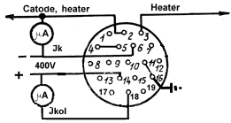
ELECTRODES-TO-LEADS CONNECTION DIAGRAM
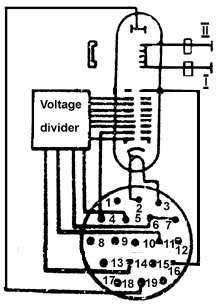 |
Designation of leads | Denomination of electrodes and other elements of diagram |
| 1, 8-10, 12, 13, 15, 17, 19 |
Free | |
| 2 | Cathode, heater | |
| 3 | Heater | |
| 4 | Second anode | |
| 5, 6, 7, 11, 14 | Voltage divider | |
| 16 | Ninth anode, slow-wave structure, case | |
| 18 | Collector | |
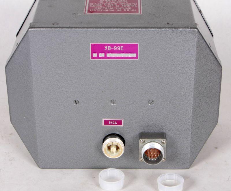
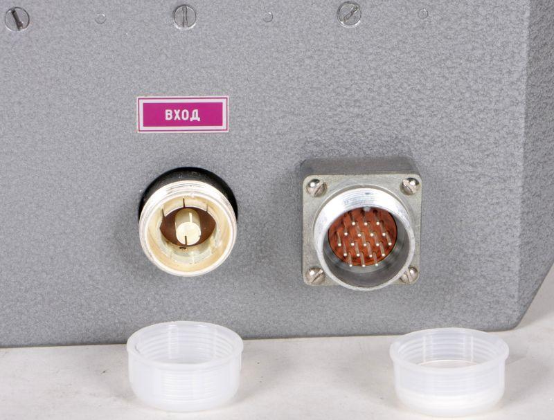
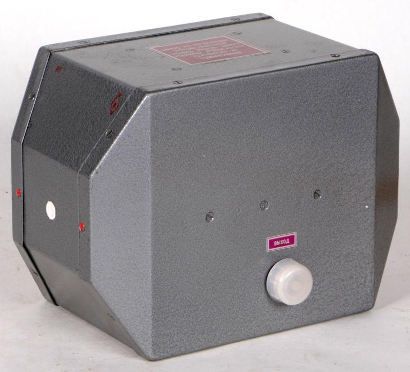
| I | Input | |
| II | Output |
Wanderfeldröhre UV-99E, УВ-99Е
Datenblätter Wanderfeldröhre UV-99E, УВ-99Е
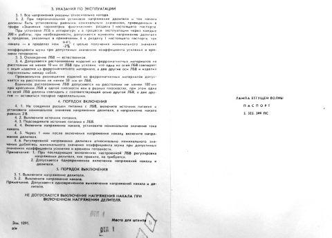
Schema Wanderfeldröhre UV-99E, УВ-99Е
OPERATION INSTRUCTIONS
All voltage are given in respect to the
cathode.
By original adjustment the divider voltage and the filament current
should be set equal to the nominal values as stated in the column
"Significances of parameters actual" of the section I of the present
certificate.
When mounting the TWT in apparatus and in the operating process in
every 200 h of operation, in case of need, it is permitted to change
the divider voltage in the limits indicated in the note 4 of the
section I of the present certificate, the filament current in the
limits of nom +4%/-2% in order to get the minimum value of the noise
factor by allowable values of the power gain and the total starting
time.
The TWT has the natural cooling.
All tools used in operation with the TWT should be made of nonmagnetic
material.
Operating place (apparatus pad) for the TWT and the fixtures must be
made of nonmagnetic materials.
It is permitted to place products of ferromagnetic materials at the
distance not less than 10 mm from the TWT provided that one of the axes
of the TWT is aligned with the axis of the product of ferromagnetic
material and two other axes of the TWT and of the product are parallel
among themselves.
The arbitrary position of the products of ferromagnetic materials is
allowed at the distance not less than 50 mm from the TWT.
It is permitted the relative position of the TWTs at the distance not
less than 100 mm when fixing the TWTs in one plane or in different
planes and one of the axes of the TWT must coincide with the
corresponding axis of another TWT and two others are parallel in pairs.
To every TWT the special unclapper 4.099.000 is enclosed which is used
for the improvement of high frequency contacts what is reached by the
insertion of it against the stop in turn in every coaxial input. During
these operations the rotation of the unclapper round the axis is not
permitted.
SWITCH ON PROCEDURE
Without connecting the connector supply to the TWT, switch on
the power supply and the nominal value of the divider voltage and the
filament voltage is equal to 2 V.
Switch off the power supply.
Connect the power supply to the TWT.
Switch on the filament voltage, set the nominal value of the filament
current.
In 1 min after switching on of the filament voltage switch on the
divider voltage.
Adjusting the divider voltage regarding the nominal value reach the
minimum value of the noise factor at the allowed values of the power
gain and the total starting time.
Notes:
- By repeated switching on of the adjusted TWT the adjustment of divider voltage is not required as a rule.
- It is permitted to switch on the filament voltage and the divider voltage simultaneously.
SWITCH OFF PROCEDURE
Switch off the divider voltage.
Switch off the filament voltage.
Note: It is permitted to switch off simultaneously the filament voltage
and the divider voltage.
Allgemeines zur Wanderfeldröhre:
Die Wanderfeldröhre gehört zu den Laufzeitröhren.
Eine Laufzeitröhre ist eine Elektronenröhren zur Erzeugung oder -Verstärkung von Mikrowellen. Laufzeitröhren finden also ihre Anwendung in der Hochfrequenztechnik.
Bei den Laufzeitröhren sind die Entladungssyteme so konstruiert, daß Laufzeiteffekte das Funktionieren der Röhre bewirken.
Zunächst wird eine homogene Elektronenströmung konstanter Geschwindigkeit erzeugt, deren Elektronen dann einem steuernden elektrischen HF-Feld ausgesetzt werden, in dem sie je nach Startphase beschleunigt oder verzögert werden.
Bei den Langzeitröhren unterscheidet man zwischen Triftröhren und Lauffeldröhren.
In der Praxis verwendete Laufzeitröhren sind Zweikammer- und Mehrkammerklystrons, Wanderfeldröhren, Rückwärtswellenröhren und Magnetrons sowie gewisse Hybridformen wie Wanderfeldklystrons.
Die Wanderfeldröhre dient der Verstärkung elektrischer Signale. Der Elektronenstrahl wird durch ein nicht mitgezeichnetes homogenes axiales Magnetfeld, herrührend von einem auf möglichst gewicht- und raumsparende Weise gestalteten Elektro- oder Permanentmagneten, oder auch von einem periodischen Permanentfeld, fokussiert und zum Elektronenauffänger geführt. Die zu verstärkende HF-Leistung wird katodenseitig auf die Wendelleitung gekoppelt, wohingegen die verstärkte HF-Leistung kollektorseitig ausgekoppelt wird.
Wanderfeldröhren werden wegen ihrer guten Linearität (Breitbandeigenschaften) und Rauscharmut und wegen des großen Leistungsspielraumes mannigfaltig eingesetzt, z.B. in Bodenstationen für Satellitenfunk mit Dauerstrichleistungen im kW-Bereich, als Satellitenröhren (bis herab zu 20 W interessant; 650g Masse) und für Richtfunktechnik (2700 Kanäle bei 6 ... 7 GHz) sowie für die Radar-Impulstechnik mit Impulsleistungen bis zu mehreren MW. Die Wanderfeldröhre ist ein weit verbreitetes Bauteil in der Radartechnik.
Der Frequenzbereich der Verstärkung ist kleiner als 0,05 dB x MHz hoch -1 im ganzen Bereich, bei optimaler Frequenz sogar noch eine Zehnerpotenz geringer.
Die Zuverlässigkeit der Wanderfeldröhren ist groß, die Lebensdauer dieser Laufzeitröhren liegt bei Größenordnungen von 20 000 Stunden.
