

- U-I-R-Messtechnik
- Signalgeneratoren
- Frequenzmesser
- Oszilloskope
- Analyzer & Wobbler
- Leistungsmesstechnik
- R-L-C-Messtechnik
- Prüftechnik, Spezialmesstechnik
- Energieversorgung
- Funktechnik
- Radar & GHz
- NF & HiFi
- Licht & Optik
- Steuer- & Regelungstechnik
- Telefonie & Kommunikation
- Mechanik
- Avionik
- Sammeln & Seltenes
- Bauelemente
- ...
- Röhrenliste
- Manuals & Schaltpläne
- sonstiges...
Informationen

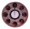
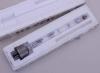
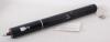
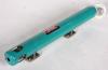
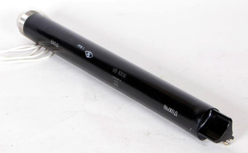
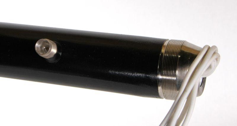
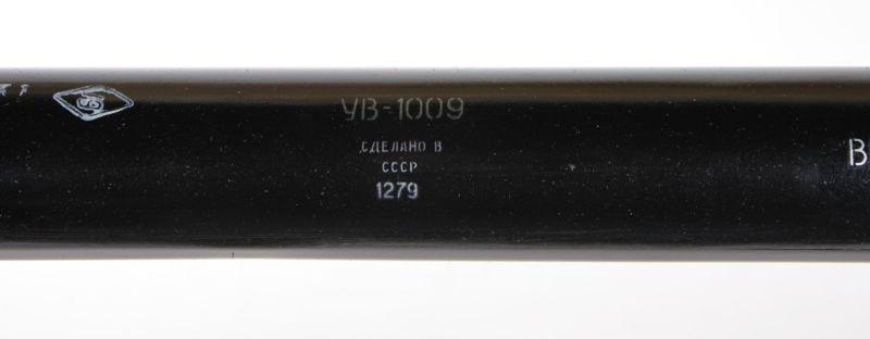
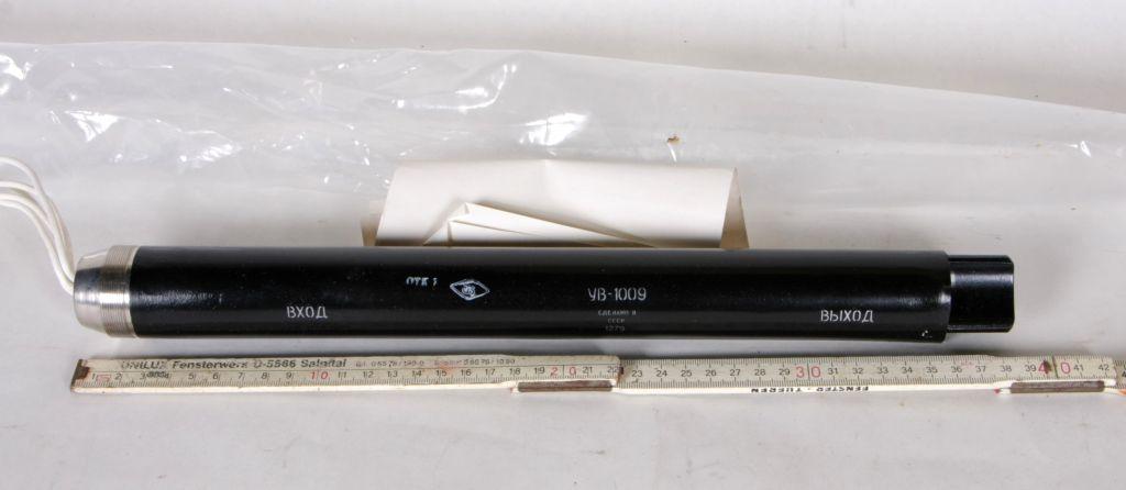
Wanderfeldröhre UV-1009
Art.Nr.: roe-wan-0003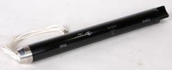


Hochfrequenz- Leistungsverstärker UV-1009, russische Bezeichnung УВ-1009.
Technical datas below.
Wanderfeldröhre UV-1009, UW-1009, УВ-1009
* Hochfrequenz- Leistungsverstärker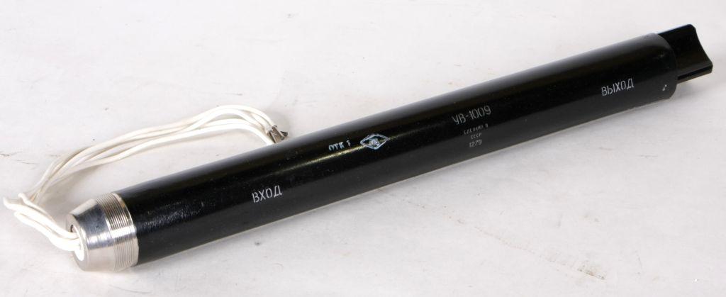
Datenblätter Wanderfeldröhre UV-91, УВ-91
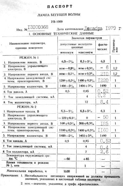
Technische Daten Wanderfeldröhre UV-1009 :
TRAVELLING-WAVE TUBE UV-1009
PRINCIPAL TECHNICAL DATA
| Denomination of parameter, measurement unit | Significances of parameters | ||
| allowable operating | actual | ||
| minimal | maximum | ||
| Operating frequency range, MHz | 3730-5350 | – | 3730-5350 |
| Behaviour N1 | |||
| 1. Filament voltage, V | 6.3-5% | 6.3+5% | 6.3 |
| 2. Control electrode voltage, V | nom-0.5% | nom+0.5% | |
| 3. First anode voltage, V | nom-0.5% | nom+0.5% | |
| 4. Slow-wave structure voltage, approximately, V | nom-0.5% | nom+0.5% | |
| 5. Collector voltage, V | 1400-5% | 1400+5% | 1400 |
| 6. Filament current, A | 0.5 | 0.85 | |
| 7. Slow-wave structure current, µA | – | 4 | |
| 8. Collector current, µA | – | 12 | |
| 9. Power gain in linear behaviour, dB | 28 | – | |
| 10. Gain flatness, dB | – | 7 | |
| Behaviour N2 | |||
| 1. Filament voltage, V | 6.3-5% | 6.3+5% | 6.3 |
| 2. Control electrode voltage, V | -100±0.5% | 0 | |
| 3. First anode voltage, V | 100±0.5% | 300±0.5% | |
| 4. Slow-wave structure voltage, approximately, V | 1100±0.5% | 1400±0.5% | |
| 5. Collector voltage, V | 1400-5% | 1400+5% | 1400 |
| 6. Filament current, A | 0.5 | 0.85 | |
| 7. Slow-wave structure current, µA | – | 4 | |
| 8. Collector current, µA | – | 7 | |
| 9. Power gain, dB* | |||
| Ambient temperature, °C | -60 | +85 | – |
| Total starting time in the behaviour N1, min, min | – | 1 | – |
| Minimum operating time, h | 1000 | – | – |
Notes:
- Instability of the supplying voltage must not exceed the significances indicated in the present table.
- Non-nominal significance of a parameter indicated in the column "Significances of parameters actual".
- * The behaviour N2 is chosen by the power gain of 10 dB in the range point corresponding to the minimum value of the power gain.
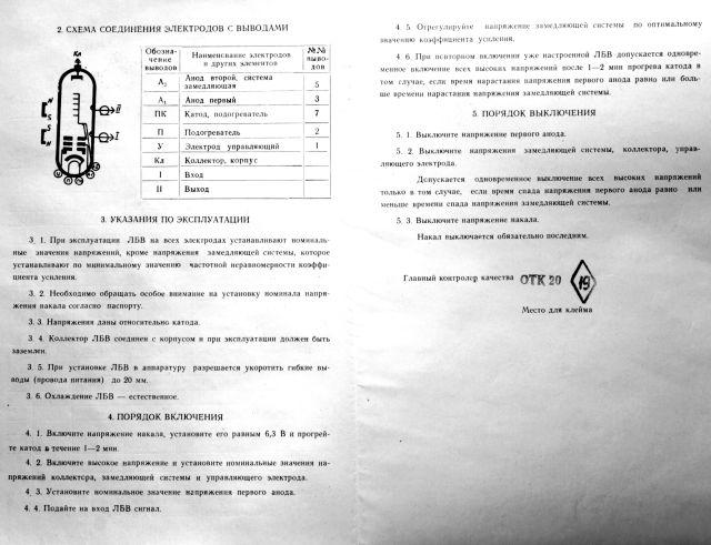
ELECTRODES-TO-LEADS CONNECTION DIAGRAM
 |
Designation of leads | Denomination of electrodes and other elements of diagram | Nos. of leads |
| A2 | Second anode, slow-wave structure | 5 | |
| A1 | First anode | 3 | |
| PK | Cathode, heater | 7 | |
| P | Heater | 2 | |
| Y | Control electrode | 1 | |
| Kl | Collector, case | ||
| I | Input | ||
| II | Output |
OPERATION INSTRUCTIONS
During the TWT operation all electrode voltage must be set to the nominal values excluding the slow-wave structure voltage which is adjusted by the minimum value of the gain flatness.
The nominal electrical regime is chosen by the producer for a given specimen of the TWT in the following limits:
| filament voltage of | 6.3 V; |
| collector voltage of | 1400 V |
| VSWR of the load not more | than 3 |
| Behaviour N1 | |
| control electrode voltage from | -50 to 0 V; |
| first anode voltage from | 150 to 300 V; |
| slow-wave structure voltage from | 1200 to 1400 V; |
| Behaviour N2 | |
| control electrode voltage from | -100 to 0 V; |
| first anode voltage from | 100 to 300 V; |
| slow-wave structure voltage from | 1100 to 1400 V; |
All voltages are given relatively the cathode.
Special attention should be paid to setting the nominal filament voltage as stated in the certificate.
The TWT's collector is connected to the case and during operation must be grounded.
It is allowed to shorten the flexible leads of the TWT supply up to 20 mm.
The supply circuit must provide the minimum inrushes of the slow-wave structure current when switching on and switching off the high voltage and the minimum inrush of the filament current when switching on the filament voltage (not more than threefold nominal value of the filament current).
To prevent the TWT from the accidental disturbances of the supply regime in the supply circuit of the slow-wave structure it is necessary to set the relay for the maximum current which should remove the high voltages by the slow-wave structure current more than 4 mA.
By the TWT operation it is necessary to observe all requirements of operation and safety regulations for the servicing of the electrical installations with the voltage over 1000 V.
It is forbidden to work with the ungrounded TWT case. It is forbidden to connect and to disconnect the TWT supply leads to the power supply by switched - on supplying voltages.
By servicing the TWT the mechanical injuries and the approach of any ferromagnetic materials at the distance less than 30 mm from the TWT case and magnetic field sources at the distance providing the value of their magnetic field on the TWT surface more than 30 Oe are not allowed.
It is allowed to use only the instruments of nonmagnetic materials.
It is necessary to fix the TWT in the equipment not less than in two places by means of embracing clamps of nonmagnetic materials through the elastic gaskets. It is recommended to place the clamps near high frequency coaxial leads from the inner side.
It is not allowed to fix the TWT by the high frequency coaxial leads of energy.
By the connection of corresponding connectors it is necessary to provide the safe contact between the inner connector conductors and the outer ones and the excessive forces which can twist or break the inner conductor of the high frequency matching device are not allowed.
The TWT has natural cooling.
SWITCH ON PROCEDURE
Switch on the filament voltage, set it equal to 6.3 V and heat
the cathode during 1 - 2 min.
Switch on the high voltage and set the nominal values of the collector
voltage, slow-wave structure voltage and control electrode voltage.
Set the nominal value of the first anode voltage.
Apply the signal at the TWT input.
Adjust the slow-wave structure voltage by the optimal value of the
power gain.
By repeated switching of the adjusted TWT it is allowed to switch on
all high voltages simultaneously after the cathode has been heated
during 1 - 2 min, if the increase time of the first anode voltage is
equal or more than the increase time of the slow-wave structure
voltage.
SWITCH OFF PROCEDURE
Switch off the first anode voltage.
Switch off the voltages of the slow-wave structure, collector and
control electrode.
It is permitted to switch off simultaneously all high voltages, if the
decay time of the first anode voltage is equal or less than the decay
time of the slow-wave structure voltage.
Switch off the filament voltage.
The filament voltage is sure to be switched off the last.
Allgemeines zur Wanderfeldröhre:
Die Wanderfeldröhre gehört zu den Laufzeitröhren.
Eine Laufzeitröhre ist eine Elektronenröhren zur Erzeugung oder -Verstärkung von Mikrowellen. Laufzeitröhren finden also ihre Anwendung in der Hochfrequenztechnik.
Bei den Laufzeitröhren sind die Entladungssyteme so konstruiert, daß Laufzeiteffekte das Funktionieren der Röhre bewirken.
Zunächst wird eine homogene Elektronenströmung konstanter Geschwindigkeit erzeugt, deren Elektronen dann einem steuernden elektrischen HF-Feld ausgesetzt werden, in dem sie je nach Startphase beschleunigt oder verzögert werden.
Bei den Langzeitröhren unterscheidet man zwischen Triftröhren und Lauffeldröhren.
In der Praxis verwendete Laufzeitröhren sind Zweikammer- und Mehrkammerklystrons, Wanderfeldröhren, Rückwärtswellenröhren und Magnetrons sowie gewisse Hybridformen wie Wanderfeldklystrons.
Die Wanderfeldröhre dient der Verstärkung elektrischer Signale. Der Elektronenstrahl wird durch ein nicht mitgezeichnetes homogenes axiales Magnetfeld, herrührend von einem auf möglichst gewicht- und raumsparende Weise gestalteten Elektro- oder Permanentmagneten, oder auch von einem periodischen Permanentfeld, fokussiert und zum Elektronenauffänger geführt. Die zu verstärkende HF-Leistung wird katodenseitig auf die Wendelleitung gekoppelt, wohingegen die verstärkte HF-Leistung kollektorseitig ausgekoppelt wird.
Wanderfeldröhren werden wegen ihrer guten Linearität (Breitbandeigenschaften) und Rauscharmut und wegen des großen Leistungsspielraumes mannigfaltig eingesetzt, z.B. in Bodenstationen für Satellitenfunk mit Dauerstrichleistungen im kW-Bereich, als Satellitenröhren (bis herab zu 20 W interessant; 650g Masse) und für Richtfunktechnik (2700 Kanäle bei 6 ... 7 GHz) sowie für die Radar-Impulstechnik mit Impulsleistungen bis zu mehreren MW. Die Wanderfeldröhre ist ein weit verbreitetes Bauteil in der Radartechnik.
Der Frequenzbereich der Verstärkung ist kleiner als 0,05 dB x MHz hoch -1 im ganzen Bereich, bei optimaler Frequenz sogar noch eine Zehnerpotenz geringer.
Die Zuverlässigkeit der Wanderfeldröhren ist groß, die Lebensdauer dieser Laufzeitröhren liegt bei Größenordnungen von 20 000 Stunden.