


Sie sind hier bei www.ostron.de/Funktechnik / Sendeempfänger
- U-I-R-Messtechnik
- Signalgeneratoren
- Frequenzmesser
- Oszilloskope
- Analyzer & Wobbler
- Leistungsmesstechnik
- R-L-C-Messtechnik
- Prüftechnik, Spezialmesstechnik
- Energieversorgung
- Funktechnik
- Radar & GHz
- NF & HiFi
- Licht & Optik
- Steuer- & Regelungstechnik
- Telefonie & Kommunikation
- Mechanik
- Avionik
- Sammeln & Seltenes
- Bauelemente
- ...
- Röhrenliste
- Manuals & Schaltpläne
- sonstiges...
Informationen

Artikel 22 / 94
Artikeldetails
Impuls-Steuerstufe Radar
Art.Nr.: funk-0017
HF-Röhrenverstärker

_ico.jpg)
Impuls-Steuerstufe Radar
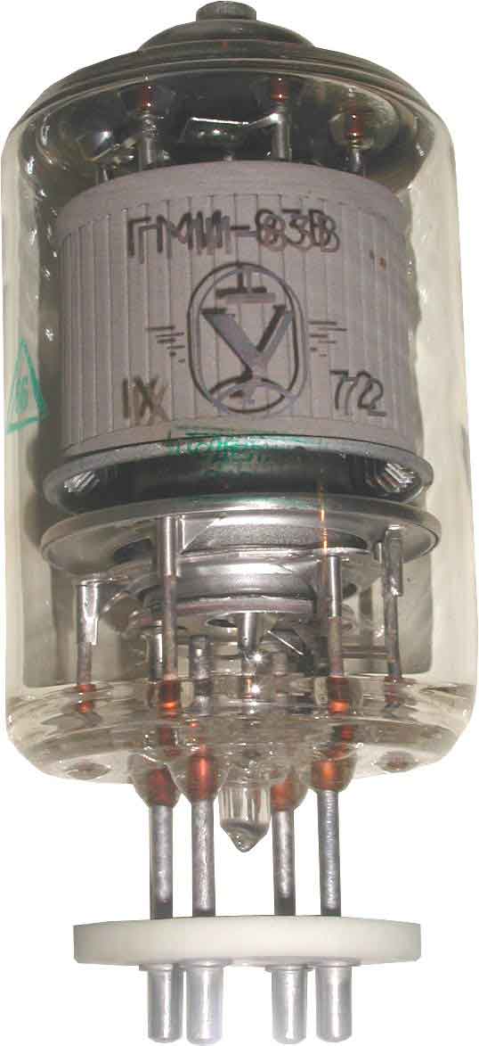
technische Daten: GMI-83V, TETRODE
The GMI-83V tetrode is used as a power amplifier in pulse modulator circuits
GENERAL
Cathode: indirectly heated, oxide-coated.
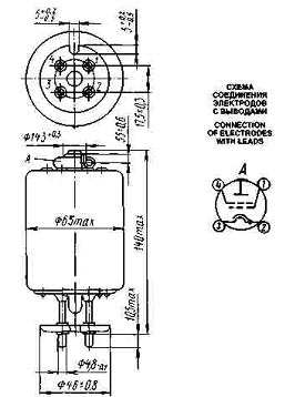
Envelope: glass, with base.
Height: at most 146.5 mm.
Diameter: at most 65 mm.
Mass: at most 300 g
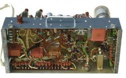
Steuerstufe aus Radargerät zur Impulsansteuerung
verbaut sind 2x GMI-83W (russische Bezeichnung ГМИ-83В)
weitere Daten sind leider unbekannt.
technische Daten: GMI-83V, TETRODE
The GMI-83V tetrode is used as a power amplifier in pulse modulator circuits
GENERAL
Cathode: indirectly heated, oxide-coated.
Envelope: glass, with base.
Height: at most 146.5 mm.
Diameter: at most 65 mm.
Mass: at most 300 g
GMI-83V, TETRODE
| OPERATING ENVIRONMENTAL CONDITIONS | |
| Ambient temperature, °C | -10 to +55 |
| Relative humidity at up to 25 °C, % | 98 |
| BASIC DATA Electrical Parameters | |
| Heater voltage, V | 25 |
| Heater current, A | 2-2.5 |
| Peak anode current, A, at least | 15 |
| Peak grid 2 current and peak grid 1 current (at anode voltage 20 kV, grid 2 voltages 1.25 kV, grid 1 voltage -800V, peak grid 1 excess voltage 250 V), A, at least | 0 |
| Cutoff voltage, V | 300-700 |
| Interelectrode capacitance, pF: | |
| input | 30-35 |
| output | 5-11 |
| transfer, at most | 1 |
| Electric strength (at anode voltage 20 kV, grid 2 voltage 1.25 kV, grid 1 voltage -800 V, peak grid 1 excess voltage 250 V, pulse duration 2 µs, pulse frequency 500 pulses/s), number of sparkings, at most | 25 |
| Electrical parameters over 500 h of service: | |
| peak anode current, A, at least | 13 |
| electric strength, number of sparkings: | |
| for 80 % of tubes, at most | 20 |
| for 20 % of tubes, at most | 50 |
| Limit Operating Values | |
| Heater voltage, V | 22.5-27.5 |
| Anode voltage, kV | 18 |
| Grid 1 voltage, kV | -1 |
| Grid 2 voltage, kV | 1.25 |
| Peak grid 1 excess voltage, V | 250 |
| Peak cathode current, A | 25 |
| Dissipation, W: | |
| anode | 60 |
| grid 2 | 9 |
| grid 1 | 3 |
| Pulse duration, µs | 5 |
| Warm up time, s, at least | 180 |
| Temperature at envelope and seals, °C | 200 |
Artikel 22 / 94
