


Sie sind hier bei www.ostron.de/Funktechnik
- U-I-R-Messtechnik
- Signalgeneratoren
- Frequenzmesser
- Oszilloskope
- Analyzer & Wobbler
- Leistungsmesstechnik
- R-L-C-Messtechnik
- Prüftechnik, Spezialmesstechnik
- Energieversorgung
- Funktechnik
- Radar & GHz
- NF & HiFi
- Licht & Optik
- Steuer- & Regelungstechnik
- Telefonie & Kommunikation
- Mechanik
- Avionik
- Sammeln & Seltenes
- Bauelemente
- ...
- Röhrenliste
- Manuals & Schaltpläne
- sonstiges...
Informationen
Kennen Sie schon... ?

Artikel 2 / 71
Artikeldetails
Impuls-Steuerstufe, Sendestufe mit GMI-6
Art.Nr.: funk-0037
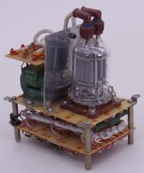
HF-Röhrenverstärker mitSenderöhren GMI-6, russische Bezeichnung ГМИ-6


Impuls-Steuerstufe, Sendestufe mit GMI-6
1, 7 - heater; 2 - grid 1 of second tetrode; 3 - grid 2; 4 - cathode and beam-forming plates; 5 - heater (centre tap); 6 - grid 1 of first tetrode; A1 - anode of first tetrode - top lead; A2 - anode of second tetrode - top lead
Sendestufe / Steuerstufe aus Radargerät zur Impulsansteuerung
mit Senderöhre GMI-6 (russische Bezeichnung ГМИ-6)
weitere Daten sind leider unbekannt.
GMI-6, TETRODE
The GMI-6 tetrode is used in pulse modulators in RF equipment
GENERAL
Cathode: indirectly heated, oxide-coated.
Envelope: glass, no-base.
Height: at most 93 mm.
Diameter: at most 48 mm.
Mass: at most 70 g
Diameter: at most 48 mm.
Mass: at most 70 g
1, 7 - heater; 2 - grid 1 of second tetrode; 3 - grid 2; 4 - cathode and beam-forming plates; 5 - heater (centre tap); 6 - grid 1 of first tetrode; A1 - anode of first tetrode - top lead; A2 - anode of second tetrode - top lead
| OPERATING ENVIRONMENTAL CONDITIONS | |
| Vibration loads: | |
| frequencies, Hz | 20-600 |
| acceleration, m/s² | 98 |
| Multiple impacts with acceleration, m/s² | 343 |
| Single impacts with acceleration, m/s² | 1,470 |
| Linear loads with acceleration, m/s² | 490 |
| Relative humidity at up to +40 °C, % | 98 |
| BASIC DATA Electrical Parameters | |
| Heater voltage, V | 12.6 |
| Heater current, A | 1-1.2 |
| Peak anode current, A, at least | 8 |
| Peak grid 2 current, A, at most | 3 |
| Cutoff voltage, V, at least | 125 |
| Interelectrode capacitance, pF: | |
| input | 11-18 |
| output | 4.2-6.2 |
| transfer, at most | 0.2 |
| Warm up time, s, at most | 60 |
| Peak anode current over 900 h of service, A, at least | 7 |
| Limit Operating Values | |
| Heater voltage, V: | |
| with parallel connection | 5.7-7 |
| with series connection | 11.4-14 |
| Anode voltage, kV | 4 |
| Grid 2 voltage, kV | 0.8 |
| Grid 1 voltage, V | 200 |
| Peak grid 1 excess voltage, V | 150 |
| Voltage between cathode and heater, V | -150 to +150 |
| Peak cathode current, A | 15 |
| Dissipation, W: | |
| anode | 15 |
| grid 2 | 3 |
| grid 1 | 1 |
| Pulse duration, µs | 5 |
| Envelope temperature, °C | 260 |
Artikel 2 / 71
