


Sie sind hier bei www.ostron.de/Frequenzmesser
- U-I-R-Messtechnik
- Signalgeneratoren
- Frequenzmesser
- Oszilloskope
- Analyzer & Wobbler
- Leistungsmesstechnik
- R-L-C-Messtechnik
- Prüftechnik, Spezialmesstechnik
- Energieversorgung
- Funktechnik
- Radar & GHz
- NF & HiFi
- Licht & Optik
- Steuer- & Regelungstechnik
- Telefonie & Kommunikation
- Mechanik
- Avionik
- Sammeln & Seltenes
- Bauelemente
- ...
- Röhrenliste
- Manuals & Schaltpläne
- sonstiges...
Informationen

Artikel 19 / 28
Artikeldetails
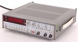
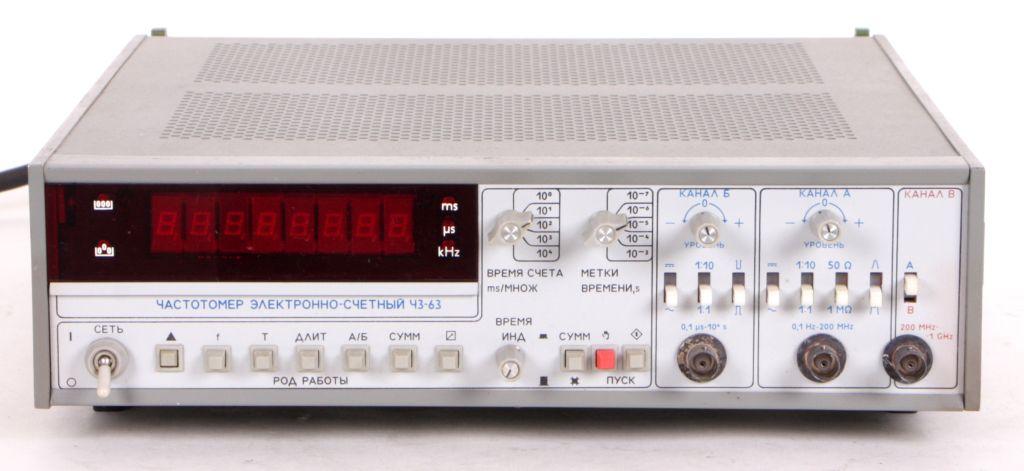
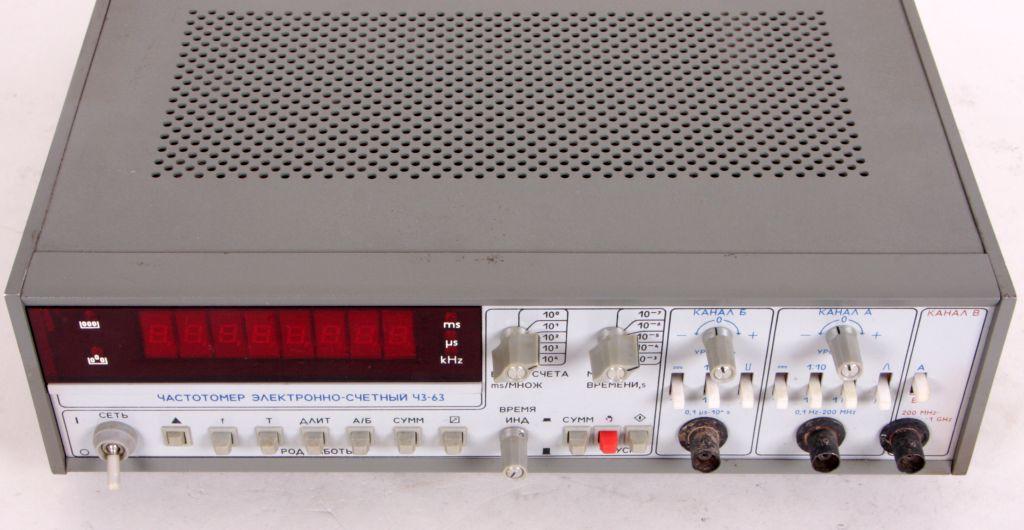
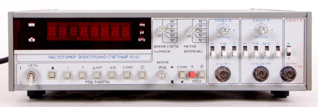
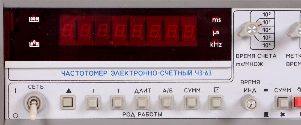
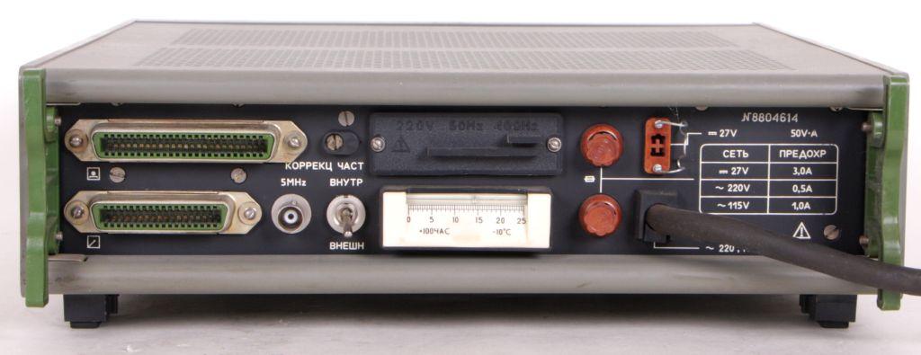
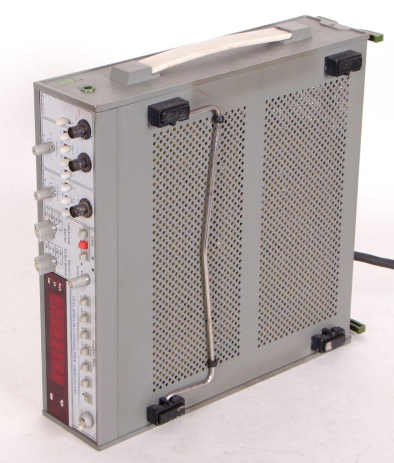
Frequenzzähler Tsch3-63, CH3-63, (Ч3-63)
Art.Nr.: freq-0022
elektronischer Frequenzzähler Tsch3-63, russische Bezeichnung Ч3-63


Frequenzzähler Tsch3-63, CH3-63, (Ч3-63)
Der elektronische Frequenzzähler Tsch3-63, CH3-63, russische Bezeichnung Ч3-63, zum Messen elektrischer Signale mit hoher Genauigkeit, zur kontinuierlichen Messung der Frequenz der sinusförmigen Signale.
Der elektronische Frequenzzähler Tsch3-63, CH3-63, (Ч3-63), findet seinen Einsatz in der Kommunikationstechnik, in der Radio- Messgerätetechnik, in der Konstruktion, Herstellung und dem Betrieb verschiedener elektronischer Geräte und deren messtechnische Unterstützung.
technische Daten:
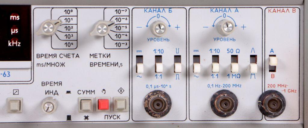
* Messbereich Frequenzen:
Sinussignal: 0,1 Hz - 1000 MHz (0,03 - 10 V eff.)
Impulssignal: 0,1 Hz - 200 MHz (0,1 - 10 V)
* Fehler Frequenzmessung: max. ± 5 · 10 -7 ± 1 Einheiten.
* Messbereich Periodendauer, Sinus- und Impulssignale: 0,1 μs - 104 s (10 MHz - 10 -4 Hz).
* Messbereich Pulsdauer: 0,1 μs - 104 s
* Eingangswiderstand, Kapazität: 1 MΩ (50 Ω), 50 pF
* Stromversorgung:
220 + 22 V, 50 ± 0,5 Hz oder 220 (115) V ± 5%, 400 + 28-12 Hz
Konstantstromquelle: 27 ± 3 V
* Stromverbrauch: 60 VA
* Empfohlener Ersatz: Ch3-77, Ch3-81, Ch3-81 / 1, Ch3-84, Ch3-84 / 1, Ch3-84 / 2, Ch3-88
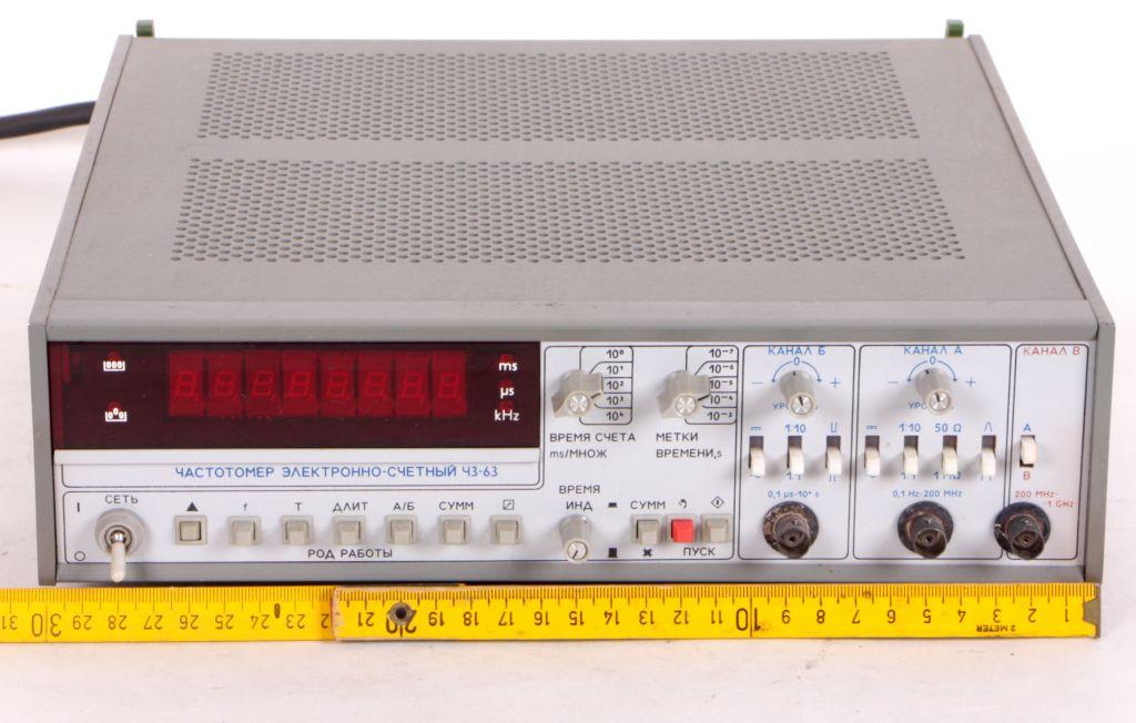
* Gewicht: 6 kg
* Abmessungen: 312 x 95 x 335 mm
Technical characteristics of devices frequency meter / electronic counter CH3-63/1:
Device operating conditions:
- Ambient temperature from -30 º C to +50 ° C;
- Relative humidity up to 98% at 25 ° C;
At input A device measures sinusoidal signal frequency and pulse signals repeat frequency of any polarity, with not more than two extreme values for the period ranging from 0.1 Hz to 200 MHz at input signal voltage:
- From 0.03 V to 10 V for sinusoidal signal;
- From 0.1 V to 10 V for pulse shape signal;
Pulse input signal minimum duration is 2.5 ns;
At input B device measures sinusoidal signal frequency in range from 200MHz up to 1000MHz with input signal voltage from 0.03 V to 3 V, in range from 1000 MHz to 1500MHz at input signal power from 0.03 mWatt to 10 mWatt;
CH3-63/1 frequency measurement relative error at sinusoidal and pulse signals (δf), in values range calculated by the formula:
δf = ± (| δ0 | + | 1 / (fmeas ∙ tcount) |),
where δ0- frequency internal quartz generator relative error or external source used instead of internal quartz generator; fmeas - measured frequency in Hz;
tcount - frequency account time (10-3s, 10-2s, 10-1s, 1s or 10s);
Nominal frequency value of quartz generator 5 MHz. Quartz generator correction frequency range at device release is at least 5 ∙ 10-17 on each side of nominal frequency;
Actual value of quartz generator frequency with device release is set with accuracy ± 1 10-8 relative to nominal frequency at the end of time required to establish mode, is equal to 2 hours, in limits;
Relative error at quartz generator frequency after time of operating mode establishing, is equal to 2hours, in limits:
A) ± 1.5 ∙ 10-7 for 30 days;
2) ± 5 ∙ 10-7 for 12 months;
30 days and 12 months time counted from frequency real value setting date with accuracy 1 ∙ 10-8 (operation mode with turn on and turn off);
Rms random variation of quartz generator frequency at an ambient temperature, maintained to within ± 1 ° C, after operating mode time is not more than:
1) 1 1010 for 1s;
2) 1 ∙ 10-10 for 10s;
Relative change in quartz generator frequency in operating temperature range of -30 º C to +50 ° C at temperature change for 1 ° C in limits ± 1 ∙ 10-9;
CH3-63/1 at input B measurements and average period of sinusoidal signal and pulse form any polarity with pulse duration is not less than 50 ns in range from 0.1 mks up to 104s (10 MHz to 10-4 Hz) at input signal voltage:
- From 0.03 V to 10 V sinusoidal signal;
- From 0.1 V to 30 V for pulse form signal;
Averaged periods number (period multiplier) - 10, 102, 103, 104;
Time marks period - 10-7, 10-6, 10-5, 10-4 and 10-3 s;
CH3-63/1 relative error in measurement period (δт) in values range, is calculated by the formula:
δr = ± (| δ0 | + | δres | + | T0/ tcount |),
where δ0 - relative error at frequency internal quartz generator or external source used instead of internal quartz generator; δres - start error, Т0 - time stamps period, s; tcount = n Tmeas - frequency account time, s; Tmeas - input signal period (measured period), s; n - number of measured periods. Accuracy start (δres) does not exceed values calculated by the formula:
δres = ± 2 ((3σsh + Un) / (S ∙ Tmeas ∙ n)),
where δres = 250 ∙ 10-6 - rms noise measurement circuit in operating frequency, at input; Un - peak noise input (measured) signal within established acceptable level, V (with random noise with an effective value σn, Un = 3σn); S - slope of voltage drop measured signal at start point, V / s; Tmeas - input signal period (measured period), s; n - number of measured periods. For sinusoidal input signal at start point with maximum error of start slope (δres) is in range of values calculated by the formula:
δres = ± ((σsh +0.3 Un) / Um ∙ n),
where Um - input signal amplitude, V; σsh = 250 ∙ 10-6 - rms noise measurement circuit in operating frequency, at input; Un - peak noise input (measured) signal within established acceptable level, V (with random noise with an effective value σn, Un = 3σn); n - number of measured periods;
CH3-63/1 measured at input B any polarity pulse duration from 0.1 mks to 10 s at pulse repeat rate up to 5 MHz and input voltage from 0.1 V to 10 V;
Device absolute error at measuring pulse duration (Δt) in range of values calculated by the formula:
Δt = ± (|δ0 tmeas | + | Δ tmeas | + | Δ tres | + T0)
where δ0 - measurement error caused by error at quartz generator frequency, s;
tmeas - measured pulse duration, s; Δtmeas τf = Ts + - error component caused by error setting start level, s; τf, Ts - rise and fall duration; Δ tres = Δ tres.f Δ tres.s + - error component depends on noise level measurement circuit, referred to input, noise level at input circuit and steepness of voltage drop at start, s; Δ tmeas.f, Δ tmeas.f - error starting channels at pulse rise and fall, s; T0 - time marks period, s;
Accuracy start channels at rise and fall (Δtres.f.s) in the range of values calculated by the formula:
Δtres.f.s = (3 σsh + Un) / Sf,s,
where σsh = 250∙10-6 - root mean square noise in the measurement circuit operating frequency, the input; Un - peak noise input (measured) signal within the established acceptable level, V (with random noise with an effective value σn, σsh = 3σn); Sf,s - slope at the point of starting the pulse rise and fall, respectively, V / s;
H3-63/1 electrical signals frequency ratio measurement from a range of higher frequencies compared (INPUT A) - 0.1 Hz to 200 MHz. The range of the lowest of the compared frequencies (INPUT B) - from 0.01 Hz to 10 MHz;
Device frequency ratio relative error (δ (f1/f2)) in the range of values calculated by the formula:
δ(f1/f2) = (|δres.n.|+|f1/(f2∙n)|),
where δres.n - error of the lower run of the compared frequencies supplied to the input of the “B”; n - number of measured periods; f1 - the lowest of the compared frequencies; f2 - the highest of the compared frequencies.
Device H3-63/1 input resistance and input capacitance to the inputs A and B isat least 1 MOhm minus 10% and not more than 50pF+10%, respectively. Device is possible to set the input impedance of the input A at 50 Ohm. Input impedance - 50 Ohm;
Frequency meter provides its specifications at the end of time required to establish the mode, which is 2 hours; time of an operating mode with no guarantee of error, or when working with an external reference frequency is less than 1 min. at an ambient temperature from +50 º C to -10 ° C and not more than 15 minutes. at an ambient temperature from 10 º C to -30 ° C;
Power supply CH3-63/1 is carried out either on AC 220V ± 22V, 50Hz ± 0.5 Hz and harmonic content up to 5% or ± 11V 220V or 115V ± 5.75 V, frequency 400 Hz ± 10 Hz, or from the source DC voltage of 27V ± 3V;
Power consumed by device from the network, at a nominal voltage do not exceed 60V ∙ A;
CH3-63/1 allows continuous operation in operating conditions for a time at least 16 hours of continuous work, which do not include the time for device operating mode establishing;
Dimensions – 312x95x342mm;
CH3-63/1 weight – is not more than 6 kg;
Mean time between failures – is at least 8000hours.

Der elektronische Frequenzzähler Tsch3-63, CH3-63, (Ч3-63), findet seinen Einsatz in der Kommunikationstechnik, in der Radio- Messgerätetechnik, in der Konstruktion, Herstellung und dem Betrieb verschiedener elektronischer Geräte und deren messtechnische Unterstützung.
technische Daten:
* Messbereich Frequenzen:
Sinussignal: 0,1 Hz - 1000 MHz (0,03 - 10 V eff.)
Impulssignal: 0,1 Hz - 200 MHz (0,1 - 10 V)
* Fehler Frequenzmessung: max. ± 5 · 10 -7 ± 1 Einheiten.
* Messbereich Periodendauer, Sinus- und Impulssignale: 0,1 μs - 104 s (10 MHz - 10 -4 Hz).
* Messbereich Pulsdauer: 0,1 μs - 104 s
* Eingangswiderstand, Kapazität: 1 MΩ (50 Ω), 50 pF
* Stromversorgung:
220 + 22 V, 50 ± 0,5 Hz oder 220 (115) V ± 5%, 400 + 28-12 Hz
Konstantstromquelle: 27 ± 3 V
* Stromverbrauch: 60 VA
* Empfohlener Ersatz: Ch3-77, Ch3-81, Ch3-81 / 1, Ch3-84, Ch3-84 / 1, Ch3-84 / 2, Ch3-88
* Gewicht: 6 kg
* Abmessungen: 312 x 95 x 335 mm
Technical characteristics of devices frequency meter / electronic counter CH3-63/1:
Device operating conditions:
- Ambient temperature from -30 º C to +50 ° C;
- Relative humidity up to 98% at 25 ° C;
At input A device measures sinusoidal signal frequency and pulse signals repeat frequency of any polarity, with not more than two extreme values for the period ranging from 0.1 Hz to 200 MHz at input signal voltage:
- From 0.03 V to 10 V for sinusoidal signal;
- From 0.1 V to 10 V for pulse shape signal;
Pulse input signal minimum duration is 2.5 ns;
At input B device measures sinusoidal signal frequency in range from 200MHz up to 1000MHz with input signal voltage from 0.03 V to 3 V, in range from 1000 MHz to 1500MHz at input signal power from 0.03 mWatt to 10 mWatt;
CH3-63/1 frequency measurement relative error at sinusoidal and pulse signals (δf), in values range calculated by the formula:
δf = ± (| δ0 | + | 1 / (fmeas ∙ tcount) |),
where δ0- frequency internal quartz generator relative error or external source used instead of internal quartz generator; fmeas - measured frequency in Hz;
tcount - frequency account time (10-3s, 10-2s, 10-1s, 1s or 10s);
Nominal frequency value of quartz generator 5 MHz. Quartz generator correction frequency range at device release is at least 5 ∙ 10-17 on each side of nominal frequency;
Actual value of quartz generator frequency with device release is set with accuracy ± 1 10-8 relative to nominal frequency at the end of time required to establish mode, is equal to 2 hours, in limits;
Relative error at quartz generator frequency after time of operating mode establishing, is equal to 2hours, in limits:
A) ± 1.5 ∙ 10-7 for 30 days;
2) ± 5 ∙ 10-7 for 12 months;
30 days and 12 months time counted from frequency real value setting date with accuracy 1 ∙ 10-8 (operation mode with turn on and turn off);
Rms random variation of quartz generator frequency at an ambient temperature, maintained to within ± 1 ° C, after operating mode time is not more than:
1) 1 1010 for 1s;
2) 1 ∙ 10-10 for 10s;
Relative change in quartz generator frequency in operating temperature range of -30 º C to +50 ° C at temperature change for 1 ° C in limits ± 1 ∙ 10-9;
CH3-63/1 at input B measurements and average period of sinusoidal signal and pulse form any polarity with pulse duration is not less than 50 ns in range from 0.1 mks up to 104s (10 MHz to 10-4 Hz) at input signal voltage:
- From 0.03 V to 10 V sinusoidal signal;
- From 0.1 V to 30 V for pulse form signal;
Averaged periods number (period multiplier) - 10, 102, 103, 104;
Time marks period - 10-7, 10-6, 10-5, 10-4 and 10-3 s;
CH3-63/1 relative error in measurement period (δт) in values range, is calculated by the formula:
δr = ± (| δ0 | + | δres | + | T0/ tcount |),
where δ0 - relative error at frequency internal quartz generator or external source used instead of internal quartz generator; δres - start error, Т0 - time stamps period, s; tcount = n Tmeas - frequency account time, s; Tmeas - input signal period (measured period), s; n - number of measured periods. Accuracy start (δres) does not exceed values calculated by the formula:
δres = ± 2 ((3σsh + Un) / (S ∙ Tmeas ∙ n)),
where δres = 250 ∙ 10-6 - rms noise measurement circuit in operating frequency, at input; Un - peak noise input (measured) signal within established acceptable level, V (with random noise with an effective value σn, Un = 3σn); S - slope of voltage drop measured signal at start point, V / s; Tmeas - input signal period (measured period), s; n - number of measured periods. For sinusoidal input signal at start point with maximum error of start slope (δres) is in range of values calculated by the formula:
δres = ± ((σsh +0.3 Un) / Um ∙ n),
where Um - input signal amplitude, V; σsh = 250 ∙ 10-6 - rms noise measurement circuit in operating frequency, at input; Un - peak noise input (measured) signal within established acceptable level, V (with random noise with an effective value σn, Un = 3σn); n - number of measured periods;
CH3-63/1 measured at input B any polarity pulse duration from 0.1 mks to 10 s at pulse repeat rate up to 5 MHz and input voltage from 0.1 V to 10 V;
Device absolute error at measuring pulse duration (Δt) in range of values calculated by the formula:
Δt = ± (|δ0 tmeas | + | Δ tmeas | + | Δ tres | + T0)
where δ0 - measurement error caused by error at quartz generator frequency, s;
tmeas - measured pulse duration, s; Δtmeas τf = Ts + - error component caused by error setting start level, s; τf, Ts - rise and fall duration; Δ tres = Δ tres.f Δ tres.s + - error component depends on noise level measurement circuit, referred to input, noise level at input circuit and steepness of voltage drop at start, s; Δ tmeas.f, Δ tmeas.f - error starting channels at pulse rise and fall, s; T0 - time marks period, s;
Accuracy start channels at rise and fall (Δtres.f.s) in the range of values calculated by the formula:
Δtres.f.s = (3 σsh + Un) / Sf,s,
where σsh = 250∙10-6 - root mean square noise in the measurement circuit operating frequency, the input; Un - peak noise input (measured) signal within the established acceptable level, V (with random noise with an effective value σn, σsh = 3σn); Sf,s - slope at the point of starting the pulse rise and fall, respectively, V / s;
H3-63/1 electrical signals frequency ratio measurement from a range of higher frequencies compared (INPUT A) - 0.1 Hz to 200 MHz. The range of the lowest of the compared frequencies (INPUT B) - from 0.01 Hz to 10 MHz;
Device frequency ratio relative error (δ (f1/f2)) in the range of values calculated by the formula:
δ(f1/f2) = (|δres.n.|+|f1/(f2∙n)|),
where δres.n - error of the lower run of the compared frequencies supplied to the input of the “B”; n - number of measured periods; f1 - the lowest of the compared frequencies; f2 - the highest of the compared frequencies.
Device H3-63/1 input resistance and input capacitance to the inputs A and B isat least 1 MOhm minus 10% and not more than 50pF+10%, respectively. Device is possible to set the input impedance of the input A at 50 Ohm. Input impedance - 50 Ohm;
Frequency meter provides its specifications at the end of time required to establish the mode, which is 2 hours; time of an operating mode with no guarantee of error, or when working with an external reference frequency is less than 1 min. at an ambient temperature from +50 º C to -10 ° C and not more than 15 minutes. at an ambient temperature from 10 º C to -30 ° C;
Power supply CH3-63/1 is carried out either on AC 220V ± 22V, 50Hz ± 0.5 Hz and harmonic content up to 5% or ± 11V 220V or 115V ± 5.75 V, frequency 400 Hz ± 10 Hz, or from the source DC voltage of 27V ± 3V;
Power consumed by device from the network, at a nominal voltage do not exceed 60V ∙ A;
CH3-63/1 allows continuous operation in operating conditions for a time at least 16 hours of continuous work, which do not include the time for device operating mode establishing;
Dimensions – 312x95x342mm;
CH3-63/1 weight – is not more than 6 kg;
Mean time between failures – is at least 8000hours.
Artikel 19 / 28
